www.gkos.net

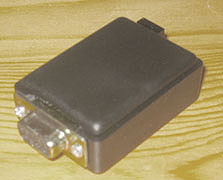
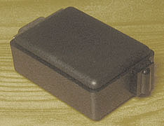
Connector side - IR Receiver side
Old software:
PIC Software: gpda100g.hex (.asm - default mode = GKOS IR byte mode) - 9 Nov 2005
PC Driver software: gdrv21c.exe - 26 May 2005 - (Beta / 9 Nov 2005: gdrv22beta.exe)
New recommended software (PIC hex file and PC Driver - 21 March 2007):
PIC Software: gpcr102.hex (gpcr102.asm)
PC Driver gkosw (Both QWERTY SDF/JKL input and COM port input from PIC)
This circuit connects the GKOS keyboard to the COM port of the PC either directly or by a wireless infrared link. No external power is needed. If your PC (e.g. laptop) does not have a serial COM port, purchase a USB/Serial port converter cable.
Use the Universal GKOS IR Keyboard of Building Project 3 for IR transmission, or you can use the GKOS IR keyboard+mouse implementations of Building Project 2 (Remote 1 or 2). A GKOS keyboard can also be connected directly as shown in red above. In the latter case, the keyboard consists only of the six switches (GKOS keys) shown. - The operating mode of the transmitting remote Universal GKOS IR Keyboard can be either GKOS Chord IR mode, turn on by [SYMB] [Ctrl] c [ENTER], or GKOS Keycode IR mode: [SYMB] [Ctrl] g [ENTER]. The Chord IR mode (sending keyboard status continuously) is more robust to IR interference, like IrDA signals from laptops, than Keycode IR mode (one byte per character).
The PIC software is the same as that for the Universal GKOS IR Keyboard. Only the sleep function has been disabled and the default mode has been changed before assembling asm to hex (see around line 722 of the asm file). Both mouse and keyboard functions are supported, as well as chordons and 59 shortcuts. All three types of GKOS IR packets can be received (Chord, Keycode and Mouse Packets). The driver is for Windows 95/98/NT/2000/XP OSs.
This circuit has been tested on a Win2000 laptop that has ±6V signal levels on TXD/DTR/RTS lines and on a WinXP desktop with ±11.5V signal levels, both when unloaded, and ±5.7V and ±8.7V when loaded by this circuit. Operation was checked also on two more laptops (Win95 and Win98 OSs). The interface and the driver (gdrv21b.exe up) operated great on all.
The zener diode must be of low power type reaching its nominal voltage at low current levels. Its second function is to stop negative voltage from reaching the PIC while the COM port is closed (DTR off: laptops 0V, desktops -11.5V). Be careful with your solderings and joints and double-check everything before connecting to the PC!
Please note that the left-hand part of the schematic, i.e. power feed from the serial port and the voltage level adjustment from PIC to RS232, has a very low component count compared to circuits commonly proposed for these purposes on the internet. Nevertheless, this design works fine with RS232 signal levels typical for laptops and desktops.
Keywords:
PC serial COM port RS232 connector for PIC 16F876 infrared receiver interface with no external power source. IR PIC power feed from serial port.
Seppo Tiainen 18 August 2005, updated 7 March 2006, 7 May 2006, 21 March 2007.
Character set: